Racks
The Rack module in SmartDoc allows you to visually document the contents of each server rack for your clients. Using an interactive graphical editor, you can place equipment unit by unit, manage power distribution and cabling, and maintain an accurate representation of the physical infrastructure in each server room.
Overview
The Rack module is designed for systems technicians and administrators who maintain server rooms on behalf of clients. It bridges the gap between network monitoring tools (which view equipment logically) and physical reality (which machine is in which slot of which rack in which room).
Each rack is:
- Associated with a client and a specific physical location (building, floor, room, row)
- Visualized front and rear simultaneously
- Linked to SmartDoc assets: each piece of equipment can point to its corresponding asset record
- Calculated in real time: total power consumption, BTU, and fill rate
Key Features
Interactive Visual Editor
The rack editor is a full-screen application that displays a precise SVG representation of the rack. You can:
- Place equipment by drag-and-drop into rack units (U)
- Switch between front view, rear view, or both sides simultaneously (side-by-side view)
- Move equipment to another position or to another rack
- View the thermal dissipation heat map
- Overlay a real photo of the rack on the diagram for comparison
Multi-Site and Multi-Rack Management
The rack list allows you to manage your entire rack inventory across all clients from a single view. Filters by client, status, and location let you quickly find a specific rack.
Automatic Calculations
The editor automatically calculates in real time:
- Used units on the front and rear separately
- Power consumption in watts (sum of active equipment)
- Thermal dissipation in BTU
- Occupancy rate relative to the rack's total capacity
Asset Linking
When adding equipment to a rack, it can be linked to an existing SmartDoc asset record. The asset information (hostname, IP addresses, MAC addresses) is then displayed directly on the graphical representation of the equipment in the editor.
Import from Hudu
An import button allows you to retrieve rack data from an existing Hudu instance, facilitating migration to SmartDoc.
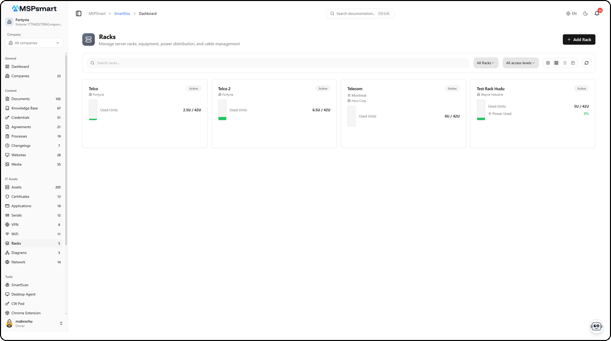
Rack List Interface
Navigation
Access via the SmartDoc sidebar: SmartDoc > Racks
Display Modes
Four display modes are available:
| Mode | Description |
|---|---|
| Small cards | Very dense grid, up to 6 columns, name and status only |
| Medium cards | 4 columns, with location and capacity indicators |
| Large cards | 3 columns, full view with power, BTU, free units |
| Table | One row per rack with all columns |
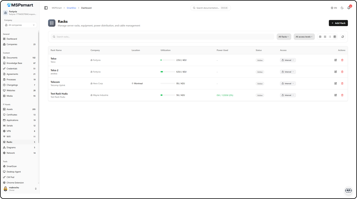
The table view displays all racks with their detailed information. Each row shows the rack name with its description, client company, location (e.g., Montreal), utilization as a progress bar (e.g., 2.5U / 42U, 6.5U / 42U), power used (e.g., 0W / 1200W), status (Active), and access level (Internal). The Actions columns provide quick access to edit or delete the rack.
Available Filters
- Text search: on name, location, and notes
- Client filter: shows only racks for a given client
- Status filter: Active, Maintenance, Decommissioned, Planned
- Access level filter: Internal, Client
Actions from the List
- Click on a card or row: opens the rack editor in a new tab
- Eye icon: quick preview without leaving the list
- Pencil icon: direct opening of the editor
- Trash icon: deletion with confirmation
- "New rack" button: opens the creation dialog
Creation Dialog
The + Add Rack button opens a creation dialog that lets you define the basic parameters of the new rack before opening the editor.
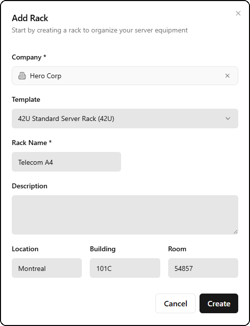
The form includes:
- Company — Select the associated client
- Template — Rack template to use (e.g., 42U Standard Server Rack), which pre-fills dimensions and default equipment
- Rack Name — Descriptive name for the rack (e.g., Telecom A4)
- Description — Optional detailed description
- Location, Building, Room — Precise physical location (e.g., Montreal, 101C, 54857)
After confirmation, the editor automatically opens in a new tab.
Rack Editor
The rack editor opens in a dedicated full-screen tab with its own toolbar. The header displays the rack name (e.g., Telco 2), its capacity (42U), and the number of devices (6 devices). Three visualization modes are available.
Front View
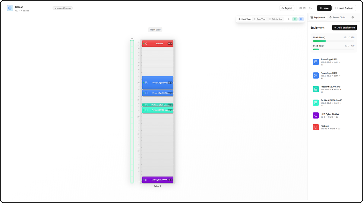
The front view displays the graphical representation of the rack with equipment positioned at their exact rack unit (U) location. Each piece of equipment is represented by a colored block showing its name, position, and height. The right side panel displays the equipment list with their positions (e.g., PowerEdge R630 U26.5-27.5, both, 2U), as well as utilization bars: Used (Front) 13U / 42U and Used (Rear) 6U / 42U.
Rear View
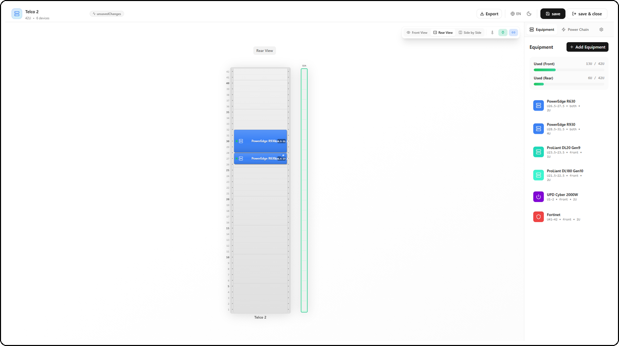
The rear view shows equipment installed at the back of the rack. Only equipment configured as rear-facing or pass-through (both) is visible. In this example, the PowerEdge R630 and R930 servers appear because they occupy both sides.
Side by Side View
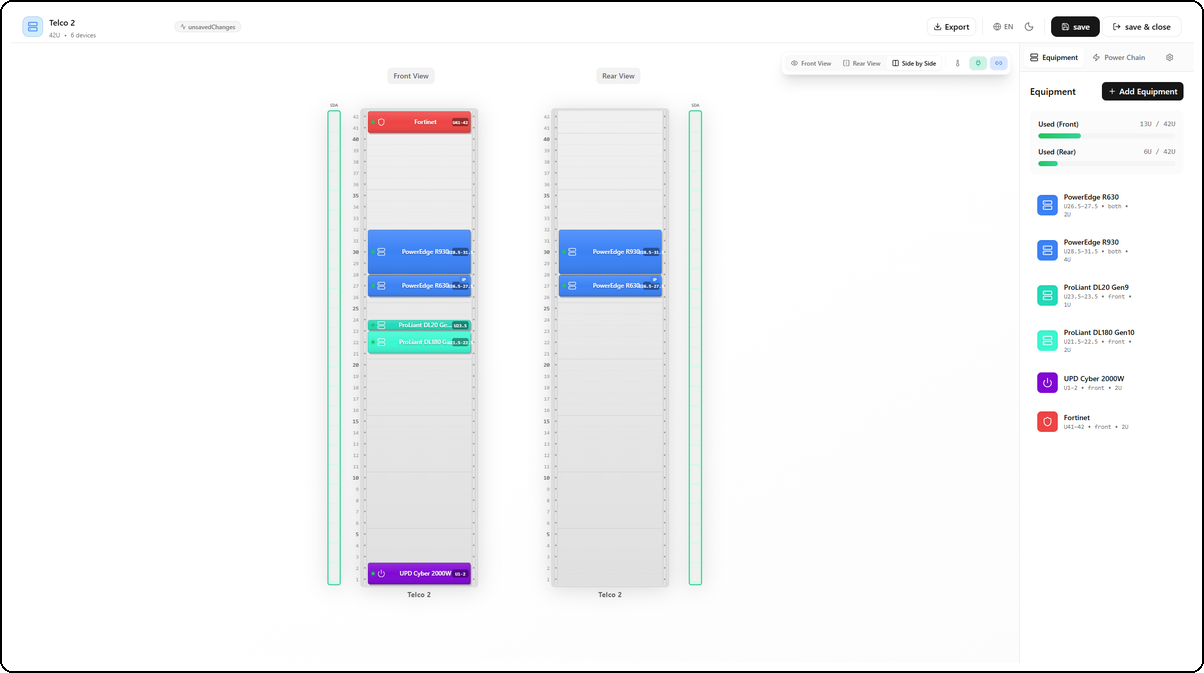
The side-by-side view displays the front and rear of the rack simultaneously, allowing you to visualize the entire infrastructure at a glance. This is the recommended mode for verifying the consistency of pass-through equipment placement.
Main Toolbar
| Button | Function |
|---|---|
| Save | Saves all current changes |
| Front view | Displays only the front of the rack |
| Rear view | Displays only the rear |
| Side-by-side view | Displays both sides simultaneously |
| Heat map | Visualizes BTU dissipation by zone in the rack |
| Show PDUs | Hides or shows power distribution units |
| Show asset info | Hides or shows linked asset data |
| Photo overlay | Enables/disables overlay of a real photo |
| Photo opacity | Slider to adjust overlay opacity (0-100%) |
| Export | Downloads the SVG image or generates a PDF |
| Exit | Returns to the rack list |
Side Panels
The editor has a configuration panel on the right side, with several tabs:
- Equipment: lists rack equipment, allows adding or modifying items
- Power: PDU and electrical connection management
- Cables: port connection management
- Photos: associating photos with the rack
- Settings: general rack configuration (dimensions, unit numbering direction, etc.)
Unit Numbering
The numbering direction can be configured:
- From the bottom: unit 1 is at the bottom of the rack (most common convention)
- From the top: unit 1 is at the top of the rack
Equipment Management
Supported Equipment Types
| Type | Description |
|---|---|
| Server | Physical servers |
| Switch | Network switches |
| Router | Routing equipment |
| Firewall | Physical firewall |
| PDU | Power distribution unit (in the rack diagram) |
| UPS | Uninterruptible power supply |
| Storage | SAN/NAS storage arrays |
| Patch Panel | Patch panel |
| KVM | KVM switch |
| Cable Management | Cable managers, organizers |
| Blank Panel | Blank panel (empty U cover) |
| Telephony | Telephone equipment |
| Other | Generic type |
Placing Equipment
To add equipment, click the + Add Equipment button in the side panel. A dialog opens with all the necessary fields.
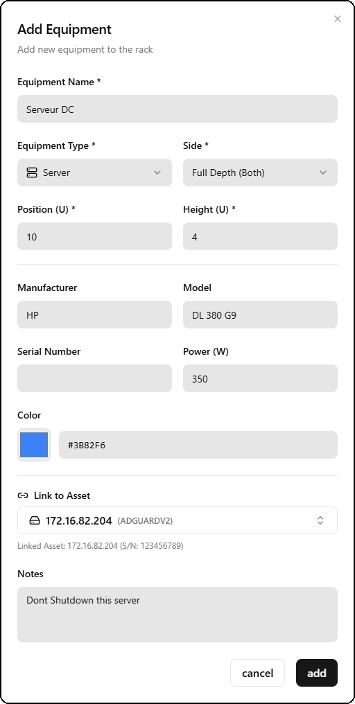
The form includes:
- Equipment Name — Name of the equipment (e.g., Serveur DC)
- Equipment Type and Side — Type (Server, Switch, Firewall, UPS, etc.) and installation side (Front, Rear, Full Depth/Both)
- Position (U) and Height (U) — Starting position in rack units and occupied height (e.g., position 10, height 4U)
- Manufacturer and Model — Manufacturer and model (e.g., HP DL 380 G9)
- Serial Number and Power (W) — Serial number and power consumption in watts (e.g., 350W)
- Color — Custom equipment color in the diagram (hexadecimal code, e.g., #3B82F6)
- Link to Asset — Link to an existing SmartDoc asset (e.g., 172.16.82.204 ADGUARDV2), which displays IP and MAC information directly on the diagram
- Notes — Free-form notes (e.g., Dont Shutdown this server)
The system automatically detects position conflicts (two overlapping pieces of equipment) and refuses placement if a conflict is detected.
Front, Rear, or Both Sides Placement
Each piece of equipment can occupy:
- Front only: visible only from the front side
- Rear only: visible only from the rear side
- Both sides: occupies both sides (pass-through equipment)
It is also possible to specify whether the equipment occupies full depth, front half only, or rear half only.
Moving Equipment
Clicking on equipment in the diagram selects it. It is then possible to:
- Enter a new U position in the form
- Change side (front/rear)
- Move to another rack (by specifying the target rack identifier)
Visual Customization
Each piece of equipment can have:
- A custom color (hexadecimal code)
- An icon from the available library
- Label display on or off
- A custom label template
Power Management (PDU)
Supported PDU Types
| Type | Description |
|---|---|
| Basic | PDU without monitoring |
| Metered | PDU with overall consumption measurement |
| Switched | PDU with per-outlet control |
| Monitored | PDU with full per-outlet monitoring |
PDU Configuration
A PDU is configured with:
- Position: left, right, rear-left, or rear-right of the rack
- Orientation: vertical or horizontal
- Input voltage: in volts (e.g., 120V, 208V, 240V)
- Input amperage: maximum current in amps
- Number of phases: 1, 2, or 3 phases
- Number of outlets: total number of available outlets
- Outlet configuration: outlet type per group (C13, C14, C19, NEMA, etc.)
- Associated UPS: connection to a UPS for redundancy calculation
- Management IP: IP address if the PDU is monitored via SNMP
Port and Cable Management
Supported Port Types
| Category | Types |
|---|---|
| Ethernet | RJ45, SFP, SFP+, QSFP |
| Fiber | LC, SC, MTP |
| Serial | RJ45, DB9 |
| USB | USB-A, USB-C |
| Power | C13, C14, C19, C20, NEMA |
| Other | Generic |
Adding Ports to Equipment
For each piece of equipment, individual ports can be added with:
- Port number and name
- Connector type
- Side (front or rear)
- Cable type and color
- Cable length in meters
- Cable label
- Status (active, inactive, reserved)
- Connection speed
- Associated VLAN
Port Connection (Cabling)
The connection feature allows creating a logical link between a port on one piece of equipment and a port on another piece of equipment in the same rack. This documents the physical cabling and allows connections to be traced.
Photos and Overlays
Associating Photos
Photos can be associated with a rack in several types:
| Type | Usage |
|---|---|
| Front overlay | Photo of the front face to overlay on the diagram |
| Rear overlay | Photo of the rear face |
| General | Overall photo of the rack |
| Close-up | Detail of equipment or cabling |
| Label | Photo of a label or barcode |
Overlay Mode
When an overlay photo is associated, the "Photo overlay" button in the toolbar activates a translucent overlay of the real photo on the diagram. The opacity slider allows varying the transparency to compare the diagram with reality.
Overlay settings (opacity, X/Y offset, scale, rotation) are saved for each photo.
Rack Fields
| Field | Description | Required |
|---|---|---|
| Name | Descriptive name of the rack | Yes |
| Client | Associated client company | No |
| Template | Rack template used as the base | No |
| Location Name | Name of the datacenter or room | No |
| Address | Physical address of the location | No |
| Building | Building name or number | No |
| Floor | Floor in the building | No |
| Room | Room number or name | No |
| Row | Row number or letter | No |
| Rack Number | Rack identifier within the row | No |
| Total Units | Rack height in U (1 to 60, default: 42) | Yes |
| Width (mm) | Standard width in millimeters (default: 600) | No |
| Depth (mm) | Standard depth in millimeters (default: 1000) | No |
| Power Capacity | Maximum power in watts | No |
| Number of Phases | Number of electrical phases (1 to 3) | No |
| Voltage | Supply voltage in volts | No |
| Amperage per Phase | Available amperes per phase | No |
| Cooling Capacity | Maximum thermal capacity in BTU | No |
| Numbering Direction | Numbering from top or bottom | No |
| Rear View | Show or hide the rear view | No |
| Status | Active, Maintenance, Decommissioned, Planned | No |
| Access Level | Internal, Client | No |
| Tags | Free-form tags | No |
| Notes | Additional information | No |
Equipment Fields
| Field | Description | Required |
|---|---|---|
| Name | Equipment name | Yes |
| Equipment Type | Category (server, switch, firewall, etc.) | Yes |
| U Position | Starting rack unit (e.g., 12 for unit 12) | Yes |
| Height (U) | Number of units occupied (in 0.5U increments) | Yes |
| Side | Front, rear, or both | Yes |
| Depth | Full depth, front half, rear half | No |
| Manufacturer | Equipment brand | No |
| Model | Commercial reference | No |
| Serial Number | Serial number on the equipment | No |
| Asset Tag | Internal MSP label | No |
| Power (W) | Power consumption in watts | No |
| Redundant Power Supply | Indicates if the equipment has two power supplies | No |
| Power Source A | PDU connected to the primary power supply | No |
| Power Source B | PDU connected to the secondary power supply | No |
| Thermal Dissipation (BTU) | Heat output in BTU/h | No |
| Airflow Direction | Front to rear, rear to front, side to side | No |
| Color | Hexadecimal color code in the diagram | No |
| Icon | Display icon in the diagram | No |
| Linked Asset | Associated SmartDoc asset record | No |
| Status | Active, Inactive, Maintenance, Planned, Reserved | No |
| Notes | Additional information | No |
Rack Templates
Rack templates allow pre-filling the parameters of a new rack. SmartDoc includes system templates (non-editable) and allows the creation of custom templates per tenant.
Template Categories
| Category | Description |
|---|---|
| Standard | General-purpose rack |
| Network | Rack dedicated to network equipment |
| Servers | Rack optimized for servers |
| Storage | Rack for SAN/NAS storage equipment |
| Custom | Template created by the MSP |
Template Contents
A template defines:
- Default dimensions (units, width, depth)
- Default electrical and thermal capacities
- Pre-positioned equipment (with type, position, and height)
Export and Printing
From the editor, the Export button opens a dialog offering three output formats.

The available formats are:
- PDF — Print-ready document with all rack information, equipment inventory, and utilization statistics
- PNG — High-resolution image of the rack diagram
- CSV — Tabular export of the equipment inventory
PDF Export Preview
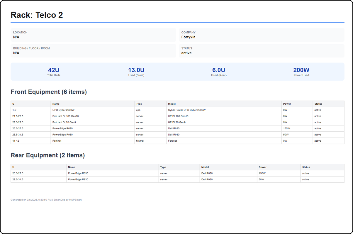
The PDF export generates a complete report including: the rack name (e.g., Rack: Telco 2), location information (Location, Company, Building/Floor/Room, Status), utilization statistics (42U Total Units, 13.0U Used Front, 6.0U Used Rear, 200W Power Used), and a detailed list of front and rear equipment in table format (U, Name, Type, Model, Power, Status). The document is timestamped with "Generated on ... | SmartDoc by MSPSmart".
The export includes both sides of the rack if the side-by-side view is active.
Best Practices
- Use rack templates to standardize new installations and save time during creation
- Link each piece of equipment to its SmartDoc asset record to benefit from automatic IP and MAC information display in the diagram
- Enter the wattage for each piece of equipment so SmartDoc can automatically calculate the electrical load and alert you if it is exceeded
- Take a photo of the real rack and associate it in overlay mode to maintain the correspondence between the diagram and reality
- Archive decommissioned equipment rather than deleting it to keep a history of the infrastructure
- Use the "Serial Number" field for each piece of equipment to facilitate maintenance interventions and warranty claims
- Document cables with color and length to simplify future interventions
Last updated: 2026-03-05